---------------------------------------------------------------------------
Please ensure you have installed Multisim software before proceeding.
Click the link here if you want to install the software : https://www.ni.com/en-my/support/downloads/software-products/download.multisim.html#312060
---------------------------------------------------------------------------
Objectives
1. To find the internal resistance and the currect sensitivity of the galvanometer.
Exercise
1. Set the potentiometer to 510 Ω. Connect the circuit as in the Figure 1.1 and keep the voltage source in minimum position such that voltage output from the voltage terminals are 0V.
2. Increase the voltage supply and the galvanometer pointer will deflect towards right hand side or left hand side. You can replace the galvanometer with the DMM/Ammeter in the Multisim. Assume Rg is 1.2 Ω for the given galvanometer. Vary the voltage supply until the galvanometer shows its maximum deflection, which the pointer should comes to 30 positions (divisions).
3. Connect the multimeter across the voltage terminal to measure the voltage and record this value as VFS.
4. Turn OFF the supply and do not disturb the voltage source. Now connect the resistance, RS and construct the circuit as in Figure 1.2. Select the 10 Ω for RS. Switch ON the instrument, then the pointer of the galvanometer will return back by a few divisions.
---------------------------------------------------------------------------
Part 1
- So what we will do is construct the circuit inside Multisim software accoding to the figures shown.
- We will start with Figure 1.1 (Circuit without Rs).
- Here, we can replace the Galvanometer with a Multimeter.
- First, set R1 to 510 Ohms.
- Adjust the DC voltage until the Multimeter shows reading of approximately 30m A (30 divisions on Galvanometer)
- Record the voltage value as VFS inside the table.
- Now, repeat the steps 4 to 6 with the same circuit by changing the value of R1 to 220 Ohms.
- After get the second value of VFS, we will proceed to the next part.
---------------------------------------------------------------------------
Part 2
- Now, construct the circuit in Multisim according to Figure 1.2.
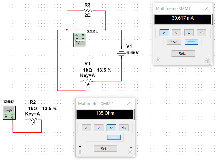
- This time, we will fix the value of VFS (The VFS values depend on the results you get in Part 1) and vary the value of Rs to 10 Ohms, 5 Ohms, and 2 Ohms. Then, we will change the value of R2 so that the Multimeter shows approximately 30m A.
- First, set VFS to the value you get in Part 1. (In my case, I get the first value of VFS=15.35V and the second value of VFS=6.65V).
- Set the value of Rs to 10 Ohms.
- Adjust the value of R2 until Multimeter shows approximately 30m A.
- Record the value of R2 in the table.
- Repeat the steps by varying the value of Rs to 5 Ohms and 2 Ohms.
- Now, repeat steps 3 to 7 by changing the value of VFS to the second answer you get in Part 1. (In my case, I will use VFS=6.65V this time).
- After recording all the values of R2 obtained, we have finished Part 2.
---------------------------------------------------------------------------
Part 3 (Calculations)
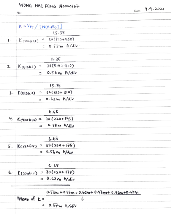
- In this part, we will calculate the values of Rg, %e, Mean of Rg, K, and Mean of K.
- Use the formula below to calculate the values of Rg :
- After getting values for all Rg, calculate %e using formula below :
- Mean of Rg is calculated by adding all the values of Rg and then divide by 6 (Since we have 6 values of Rg).
- K is calculated using the formula below :
- Mean of K is calculated by adding all the values of k and then divide by 6 (Since we have 6 values of K).
---------------------------------------------------------------------------
Results

Circuits Result using Multisim Software
Part 1
VFS when R1=220 Ohm s
Part2
Part 3
---------------------------------------------------------------------------
Discussion
1. Connect the circuit in Figure 1.3 and run the simulation for both load resistance values for 10kΩ and 100kΩ. Observe the measured voltage using a voltmeter/DMM and conclude the answer with the prove of the diagram.
Connection in Multisim :
For RL=10k Ohms
For RL=100k Ohms
- For RL=10k Ohms, U1=2.577V. For RL=100k Ohms, U1=3.295V.
- From the results observed, the value of voltage increases when the value of RL increases.
- This can be proved by using the Voltage Divider Rule (VDR).
- The formula to calculated the U1 using VDR in this question is :
- Therefore, when the value of RL increase, the corresponding resistance of R2||RL increase, and thus U1 measured will also increased.
2. Connect the circuit in Figure 1.4 and run the simulation for. The actual voltage across R2 is 7.5 V. Configure the circuit with the voltmeter has an internal resistance of 1 MΩ, 10MΩ and 100MΩ. Observe the measured voltage using a voltmeter/DMM and conclude the answer with the prove of the diagram.
Connection in Multisim :
For internal resistance of 1M Ohms :
For internal resistance of 100M Ohms :
- For volmeter internal resistance, Rm = 1M ohm, U1=7.143V
- For Rm=10M ohms, U1=7.463V.
- For Rm=100M ohms, U1=7.496V
- During the measurement, the volmeter is parallel with the measurement circuit component, R2.
- The parallel resistance of Rm of voltmeter and R2 will become less compare to value of R2 alone.
- Therefore, according to VDR, the voltage across R2 will decrease when the voltmeter is connected.
- The decrease in voltage is depending on the sensitivity of the voltmeter. (In this case, it is depending on the internal resistance of the voltmeter.)
- This effect is called voltmeter loading effect.
- The resulting error is called loading error.
---------------------------------------------------------------------------
Conclusion
In this lab, I learned to use Multisim software to construct circuit and get all the readings needed. Since now we are doing lab fully online, it is important to understand and can use the software properly. Then, I learned that in series circuit, when the value of current is fixed (in this lab part 1, the current value is fixed at 30mA) and when the value of resistance decrease, the value of voltage will also decrease. This is due to the Ohm's Law which can be represented by the formula V=IR. When shunt resistor, Rs is added and the values of voltage and current are fixed, the value of R2 will become lower. However, in the same condition where the values of voltage and current are fixed, when the value of Rs decrease, the value of R2 will also decrease.
In the exercise question 1, I know that if two resistors are connected in parallel, the corresponding resistance will decrease and the voltage across them will decrease. The value of the resistors in parallel will affect the voltage reading. This can be proved and calculated by using the Voltage Divider Rule(VDR) stated above. Lastly, in exercise question 2, I learned the voltmeter loading effect. The theory is same as in VDR but this time the voltmeter itself will act as resistor in parallel with the component and thus it cause the voltage reading get to decrease from the actual reading. The decrease in the voltage can be negligible or appreciable depending on the sensitivity of the voltmeter. The resulting error of voltmeter loading effect is called loading error.
---------------------------------------------------------------------------
Thank you for reading. Feel free to ask me if you have any questions.
---------------------------------------------------------------------------


Comments
Post a Comment