---------------------------------------------------------------------------
Please ensure you have installed ESP32 properly in Arduino IDE software before proceeding.
Click this link if you want to install Arduino IDE : https://www.arduino.cc/en/software
---------------------------------------------------------------------------
Introduction to ESP32
ESP32 is a series of microcontroller chips like Arduino. It is the advance version of ESP8266 and is loaded with lots of new features.
Below are the specifications of ESP32 :
- ESP32 is dual core. (It has 2 processors.)
- It has built-in Wi-Fi and bluetooth.
- It runs 32 bits programs.
- The clock frequency can go up to 240M Hz.
- It has a 512 kB RAM.
- This particular board has 30pins. (There is also a new version which has 36pins.)
Datasheet of ESP32 DEVKIT V1 - DOIT (Board that I will use in my lab)
---------------------------------------------------------------------------
Part 1 - Use Push Button to Control the Lighting of LED
List of components :
- ESP32 DOIT DEVKIT V1 Board
- LED
- Push button
- 330 Ohm resistor
- 10k Ohm resistor
- Breadboard
- Jumper wires
Circuit connection :
Coding in Arduino IDE :
1. Declare the pin used for push button as input ; declare the pin used for LED as output.
2. Initialize the push button state as LOW.
3. Upload the program code to ESP32.
4. If the button state is HIGH, the LED will light up and the serial monitor will print "1" ; Else, if the button state is LOW, the LED will not light up and the serial monitor will print "0".
Results :
When push button is pressed, the LED lights up.
Output in serial monitor (Remember to set the Baud rate to 115200) :
---------------------------------------------------------------------------
Part 2 : Use Touch Sensor to Control the Lighting of LED
List of components :
- ESP32 DOIT DEVKIT V1 Board
- LED
- 330 Ohm resistor
- Breadboard
- Jumper wires
Circuit connection :
Coding in Arduino IDE :1. The operation is almost the same as using push button, just the push button is replaced by touching the jumper wire.
Results :
When the wire connected to GPIO 4 is touched, LED lights up.
Output in serial monitor (Remember to set the Baud rate to 115200) :
Output in serial plotter (Remember to set the Baud rate to 115200) :
- When the wire is touched, the value of threshold will decrease.
---------------------------------------------------------------------------
Part 3 : Pulse-Width Modulation (PWM)
List of components :
- ESP32 DOIT DEVKIT V1 Board
- LED
- 330 Ohm resistor
- Breadboard
- Jumper wires
Circuit connection :
Coding in Arduino IDE :
1. The LED will light and dim automatically as the value of PWM changes.
2. When PWM value increase, the LED lights up.
3. When PWM value decrease, the LED will become dim.
Results :
Now let's use PWM to control 3 LEDs this time.
Connections :

Coding in Arduino IDE :
1. Three LEDs is assigned to different GPIOs.
2. The working of the circuit is the same as the circuit with one LED, just we add two more LEDs.
Results :
---------------------------------------------------------------------------
Part 4 : Reading Analog Inputs Using Potentiometer
List of components :
- ESP32 DOIT DEVKIT V1 Board
- Potentiometer
- Breadboard
- Jumper wires
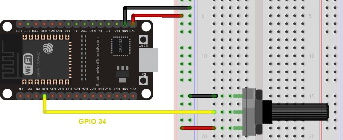
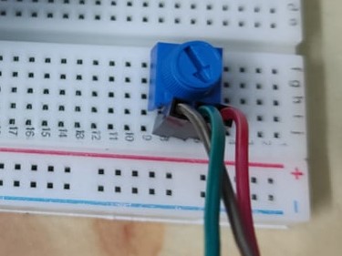
Circuit connection :

Coding in Arduino IDE :
1. The value of the potentiometer will be shown on the serial monitor.
Results :
- The minimum value of potentiometer is 0.
- The maximum value of potentometer is 4095.
- When turning the potentiometer, the value shown will change accordingly.
When the potentiometer is minimum :
When the potentiometer is at maximum :
---------------------------------------------------------------------------
Part 5 : Reading Values of Light Dependent Resistor (LDR)
List of components :
- ESP32 DOIT DEVKIT V1 Board
- Light dependent resistor (LDR)
- 10k Ohm resistor
- Breadboard
- Jumper wires
Circuit connection :
Coding in Arduino IDE :
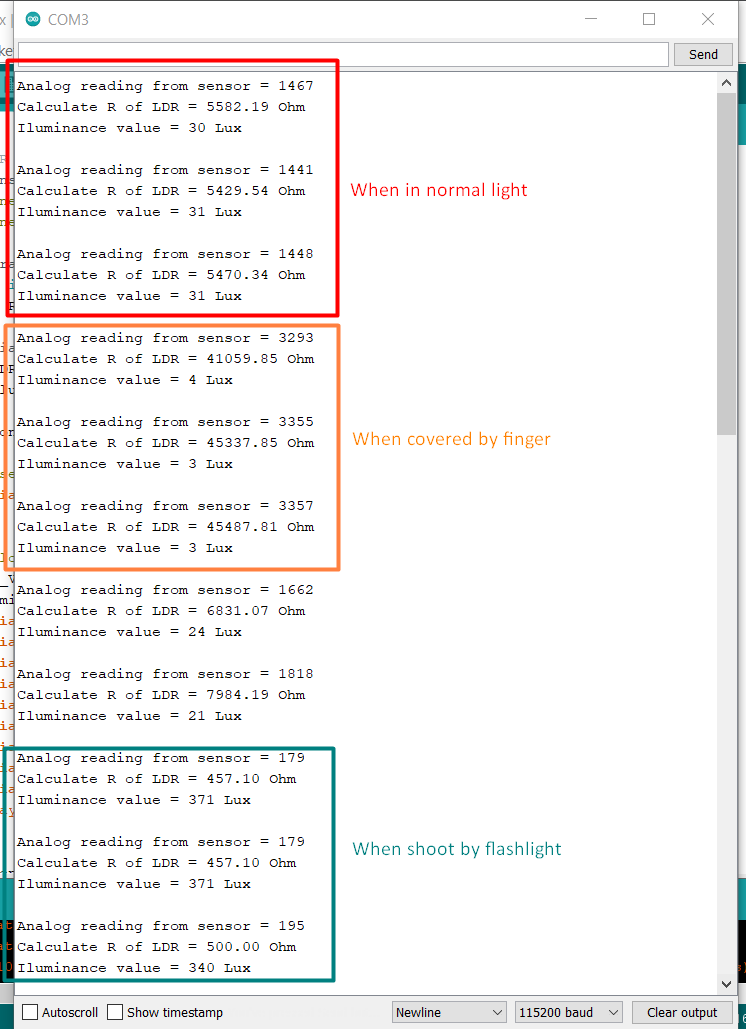
1. The analog readings will be converted to Ohm and Lux.
2. Three types of values will be shown in serial monitor.
Result :
---------------------------------------------------------------------------
Conclusion
As a conclusion, ESP32 is a microcontroller that is easy to use and it has a lot of features that are useful. In this lab, I have learned how to read the GPIOs of ESP32. I also learned to program ESP32 to show get inputs and show outputs using Arduino IDE software.
The working theory for the project is simple. First, you will assign pins of the ESP32 either as input or output inside Arduino IDE. Then, connect the components according to the coding done. After you press upload the coding from Arduino IDE to ESP32, DO NOT FORGET to press the "Boot" button on your ESP32 to overwrite the previous program code. Otherwise, your new coding will not be uploaded to the ESP32.
In Part 1, I learned to use push button as input to control the LED to light up. In Part 2, I replaced the push button input to touch sensor. This is actually just using my hand to touch the input wire to control the LED to light up. The threshold values are also shown in this part. Then, in Part 3, I learned to use LED PWM controller of ESP32 to dim LED. This is my favourite part as the LEDs can glow and dim automatically. In this part, I do 2 circuits and coding. The first one is only controlling one LED while the second one controls three LEDs at a time. In part 4, I learned to read the analog inputs of a potentiometer and the values from the potentiometer are shown on the serial monitor. The potentiometer is adjusted to change the values. In part 5, I learned to read the analog inputs of a LDR and then convert the values to resistance and iluminance and show them on the serial monitor.
*** In the next lab, another cool function(s) of ESP32 will be shown. Stay tuned! ***
---------------------------------------------------------------------------
Thank you for reading. Feel free to ask me if you have any questions.
---------------------------------------------------------------------------


Comments
Post a Comment